Code Architecture
Modules
The simulation part of ADS-IDAC consists of five modules:
- Crew Module (
src/ADSIDAC/Crew/,ReasonMachine/,Procedure/): models the response of the operating crew. - System Module (
src/ADSIDAC/System/): holds the plant state exchanged with the thermal-hydraulic solver and passes control actions to it. - Control Panel (Indicator) Module (
src/ADSIDAC/ControlPanel/): models the alarms, parameter indicators, component state indicators and controls of the control room. - Hardware Reliability Module (
src/ADSIDAC/HWReliability/,SupportSystemsReliability/): determines the timing and probability of component and support-system failures. - Scheduler Module (
src/ADSIDAC/Scheduler/,Branch/,Solver/): controls the simulation sequence, the branching and the outputs.
Under MPI an additional layer (src/ADSIDAC/ParallelExec/) distributes the sequences over ranks; see Simulation Flow.
The Scheduler Module coordinates the interactions among the other four. Event sequences generated by crew activities and by component failures are coordinated by it. The Crew Module interacts with the Control Panel Module to assess system information and to control the states of systems and components. Crew communication and the operators' actions on the system are sent to the Scheduler Module, which directs them to the corresponding modules. The System Module changes the state of a system or component following the commands it receives; these result from operator interventions or from hardware failures. The Hardware Reliability Module calculates component and system failure probabilities.
The modules, and the auxiliary objects used for data storage, are members of the single SimulationContext instance g_sim. They are listed in Simulation Flow.
Interaction from the programming perspective
The thermal-hydraulic solver calculates the system state with its own internal time step, which can be very small (for example 1E-6 s) depending on the transient. The engine is evaluated when the accumulated solver time since the last evaluation reaches 0.5 s. At that point the solver values are copied into the System Module, the control panel updates its state (parameters, components, alarms and controls) from the System Module, and the crew and reliability modules calculate their next state from the updated control panel.
The hardware reliability modules and the crew module interact only with the control panel, so all system information these modules need has to be placed on the control panel. The control panel passes the action commands it receives to the System Module, which acts on the solver in SystemModule::executeActionsToInteractWithSystem(). For RELAP5 this calls the Fortran routine finteract (src/Relap/finteract.for), which sets an interactive variable.
Branches that create new sequences are generated by the crew module and by the reliability modules. The solver and the System Module perform a best-estimate calculation and generate no branches. Alarm state changes of the control panel are registered with the branch record (BranchRecord::addSystemAlarms()), but alarms alone produce a branch point with a single branch and no new sequence.
RELAP5 is written in Fortran, and all other modules in C++. The data exchange between them is described in Fortran/C++ Interface.
Terminology
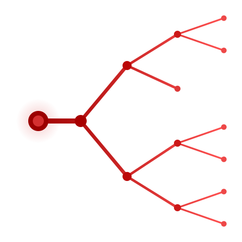
Within these pages, "simulation" means the process of generating a dynamic event tree, so terminating a simulation means stopping the entire process. A "sequence" is one scenario within the tree, so terminating a sequence means stopping the current scenario and continuing with another one.